Wednesday, March 11, 2009

Gogogogo

Okay, here's the pictures that go along with Gemma's post.

Us taping up the wires to the plexiglass


This is us testing out the ConfigApp program to set up the camera and make our touches show up on the computer. In the picture you might be able to see Peter's fingertips showing up in the window.


Things that need to get done:
  • Trim the paper/try the velum
  • Put in slats between the frames
  • Screw in top frame to bottom frame
  • Fix the position of the projector stand
  • Buy velcro so that the projector doesn't fall on the ground :)
  • Create shelf to hold onto the wires off the back corner
  • TAPFish (almost complete)
  • TAPaMOLE (all images done)
  • D&D Tabletop Game (functionality mapped out)

Tuesday, March 10, 2009

Finishing Up

Today we did some finishing touches to the hardware. We labeled all the wires and taped them down around the rails. We also made all the final changes to position and angling of the projector. Currently the projector mount was not at a fixed angle, but we got the best angle and marked it so we can alter the mount to be at that angle permanently tomorrow morning. Everything looked really nice. It read our input well, and the projection shows up nicely on the screen. I'm looking forward to having it all finished!

Sunday, March 8, 2009

Finishing the Screen

We finished up the screen today! I had given the rails (which weren't attached to the plexiglass) to Casey previously, and while moving them, some of the wires broke off. Wires were simply soldered to LEDs and left hanging. After moving and weakening the LED leads, some of them simply broke. Sadly they broke at the base of the LED and required the LEDs to be replaced. Today we replaced the broken LEDs. We designed it to allow easy access for this kind of incident, so it wasn't too much of a problem. We also taped down the wires in a way that allowed the wires to move without moving the LED leads.

To make sure everything worked, we tested each line of the parallel circuit separately.


Everything worked nicely! After making sure that each line worked individually, we wired up all the lines together, attached them to the plexiglass, and gave the whole thing a test. The LEDs were much brighter that I expected! We ran some touch programs with it, and they worked well. It was wonderful to see the whole thing working perfectly.

Thursday, March 5, 2009

One Fish, Two Fish, Red Fish... TAP FISH


App #1 of a series of apps to come!!

TAP FISH:

This is an application to simulate a "pond" with fish in it. The user interacts with the screen to make the fish do different things. As of now, no textures have been imported, so the fishes are squares and there is no background. But that will change.

Now:
Right-clicking freezes the fish in a defined radius in place
Left-clicking puts them back into motion
Left and Right clicking simultaneously causes fish in a defined radius to scatter, then attract

Later:
All clicking will be replaced by touching
A way to switch between starting/stopping or scattering/attracting

More to come !!

Mirror, mirror found behind the door in my parent's bedroom...

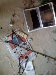
I found a mirror at home (yay!), that although it has curved edges, the rectangular area that can come out of it is 17.5x21 inches which is good enough for what we need (explanation to come).

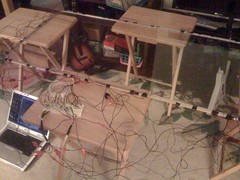
Casey and I made some measurements to figure out what the base needed to look like. We wanted the table to be about 40-44 inches high so that you would be able to stand next to it and be comfortable touching all spots on the screen. So we did a test; we measured out 40 inches away from our projector screen and held up the mirror, simulating the distance from the plexiglass screen and the...mirror. Then we moved the projector back enough so that the image would project to the right dimensions. It turned out that the projector only needed to be moved back to right underneath the screen to get to 24 inches high - an equal proportion. So the projected image onto the mirror would only need to be half the size of the desired image - 12x24. But, I should have thought about this earlier, the projector projects out at a 3:5 ratio, and our screen is 1:2, so the projection will be something more like 24x40 instead of 24x48. But, this is okay and we won't miss the extra 4 inches on both sides (which some will be covered up by the frame anyways).

So, we then had ample measurements to make the base and projector mount.

Blog on base construction coming soon!

woot.

Wednesday, March 4, 2009

Biscuits and gravy...I mean glue

Started the construction of the frame and base last night. Went to Home Depot to get 3 1x6x6 for the frame. With help from my dad we were able to cut the wood in half using his table saw and using the dimensions of the plexiglass, where able to make a frame that would cover the rails. Each piece is 51"x 27", giving an extra inch and a half around the plexiglass.


Here's both of them together


The goal is to sandwich the rails/plexiglass combination between the frames. To make sure the window doesn't move, wood blockers will be put into place. The whole thing will most likely be screwed together on the corners and where the blockers are.

The next step after that (will be worked on Thursday) will be to create the base, which will be just legs and a rectangular top, with the same dimensions as the frame, to hold it all together. Also it will need to be able to hold a mirror to bounce the projection onto the screen.

Thursday, January 29, 2009

Break Stuff!

Okay, we're almost ready to start soldering the LED's together. We bought perfboard to line the rails, but we had to cut it. We tried to use an exacto-knife to cut it first, but that was unsuccessful. Then we thought that we could cut it with a table saw or jigsaw or handsaw, but any that we tried just shattered the perfboard. (Seen in the picture)


So, we just broke it! We clamped down the perfboard under a metal bar and bent it up evenly with another metal bar so that it would snap at the spot that we wanted.

Now we have enough to go around our plexiglass!

Tuesday, January 20, 2009

Let there be light!

So we figured out what we want to do for our circuit -- we decided to use an 18V power source versus our old 30V source to make our circuit simpler and so that our potentiometers wouldn't have to take so much wattage. Thus, we have our source connected to 10 lines consisting of: a 100Ohm resistor, our 1kOhm potentiometer, and 10 IR LEDs in series.

And... guess what! It works!


10 IR LEDs in series powered with an 18V source

Next step is to wire and solder the 10 lines of LEDs and place them in the rails

Friday, January 16, 2009

More Progress

We haven't posted here for a while, so I suppose it's time for a status update. We're still having a lot of trouble trying to figure out the circuit. We did set up the railings though!

We goofed at first a little.

Whoops

Eventually we got them all done just fine.

Drilling

We took some really cool photos of the screen with an LED hooked up while we touched the other side, but now the video won't load. I'll probably need to convert the video from the Logitech program we used, but it'll be up shortly!